SCSI Hard Disk Drives — Take-Apart
October 2, 2020
This post, a rework of Apple’s Cross Family Peripherals Volume 1 (Apple p/n 072 0230) as revised on April 1991, provides take-apart directions for Apple’s SCSI Hard Disk Drives. A scan of the original document can be accessed at The Internet Archive Identifier PN_072-0230_Cross_Family_Peripherals_Volume_1.
The figures in this post show a typical 5.25-inch drive assembly. Individual drives are shown whenever differences in design could affect a procedure. When the procedure itself differs between drive models, a note appears in the text.
CASE TOP
Materials Required
No. 2 jeweler’s screwdriver
Remove
Follow the steps below to remove the case top:
Locate the two holding tabs (Figure 1, #1) on the rear of the hard disk, within the ventilation slots on either side of the top SCSI connector.
Using a jeweler’s screwdriver, press in gently on the lower end of each tab as you push the case top up slightly.
Locate the four tab holes, two on each side of the hard disk (see Figure 1, #2). Starting with the rear holes, free the tabs by gently inserting the screwdriver straight into each of the holes, nudging the case top up as you release each tab. Prying is not necessary and may damage the case.
When all tabs are released, lift the case top off the case bottom.
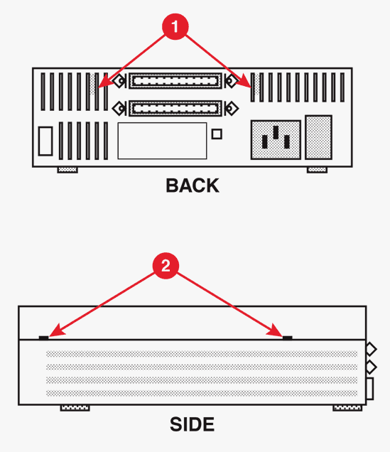 Figure 1
Replace
Follow the steps below to replace the case top:
Fit the front of the case top under the front lip of the case bottom.
Gently push the case top down, making sure the metal shields are tucked in. You will hear a click when the tabs are seated.
Power Supply
Materials Required
No. 2 jeweler’s screwdriver
Remove
Remove the power supply as follows:
- Remove the case top.
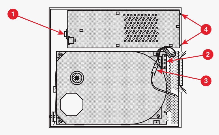 Figure 2
Push back the power supply tab (Figure 2, #1), lift up the front edge of the power supply, and rest it on the front of the case.
Disconnect the power supply connector (Figure 2, #2) from the hard disk assembly.
Note: On some hard disk assemblies, the power supply connector is located on the opposite side of the hard disk.
Disconnect the fan cable by releasing the little holding clip on the connector (Figure 2, #3).
Lift the power supply free.
Replace
Replace the power supply as follows:
Place the power supply loosely into the drive case with its front edge resting on the front edge of the case.
Connect the fan cable (Figure 2, #3). It fits only one way.
Connect the power supply connector (Figure 2, #2) to the hard disk assembly. It fits only one way.
Note: On some hard disk assemblies, the power supply connector is located on the opposite side of the hard disk.
Carefully slide the power supply toward the tabs (Figure 2, #4) on the inside back of the case bottom until the tabs fit into the holes in the power supply’s metal case.
Carefully settle the power supply into place, so that the edge of the metal bracket fits under the tab (Figure 2, #l).
Replace the case top.
VIDEO
For a comprehensive video of Apple’s Hard Disk 20SC refer to James’ video which details take-apart procedures and the recommended capacitor replacement process steps required to recondition the power supply unit. James is meticulous with his show notes which are rich with detail so I recommend you watch the video from his YouTube channel.
HARD DISK ASSEMBLY
Use the following procedure to replace any external 3.5-inch or 5.25-inch 20SC, 40SC, 80SC, or 160SC hard disk assembly. If you are replacing a 20 MB drive, keep in mind that Apple shipped two versions of this drive. The Hard Disk 20SC Version A drive and the Hard Disk 20SC Version B drive are identical, but these drives must be replaced like-for-like. To differentiate between the drives, refer to “Identifying 20SC Revision A and B Drives.”
Materials Required
No. 2 jeweler’s screwdriver Needlenose pliers
Remove
Remove the hard disk assembly as follows:
Remove the case top.
Push back the large tab (Figure 3, #1), slide the hard disk up, and rest it on the front edge of the case.
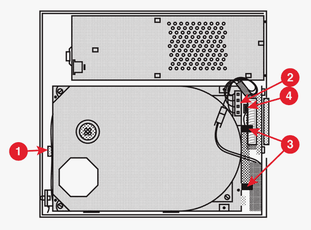 Figure 3
Disconnect the power supply connector (Figure 3, #2).
Note: On some hard disk assemblies, the power supply connector is located on the opposite side of the hard disk.
Open the end tabs (if present) on the HDA-to-case cable connector (Figure 3, #3), and disconnect the cable from the hard disk assembly.
Disconnect the SCSI select switch connector (Figure 3, #4).
Lift the hard disk assembly out of the case.
Note: External 20 MB and 160 MB drives are returned to Apple in their original mounting frames. If you are replacing an external 20 MB or 160 MB drive, skip the following steps for removing the mounting frame and go to the Replace procedure.
Note: The 3.5-inch hard drives are mounted on four screws near the center of the metal frame.
Turn the drive over, and remove four screws (Figure 4, #1) from the bottom edge of the metal mounting frame.
Disconnect the LED cable and SCSI select cable from the hard disk assembly, and set the metal mounting frame aside. Use this mounting frame to install the service (replacement) module.
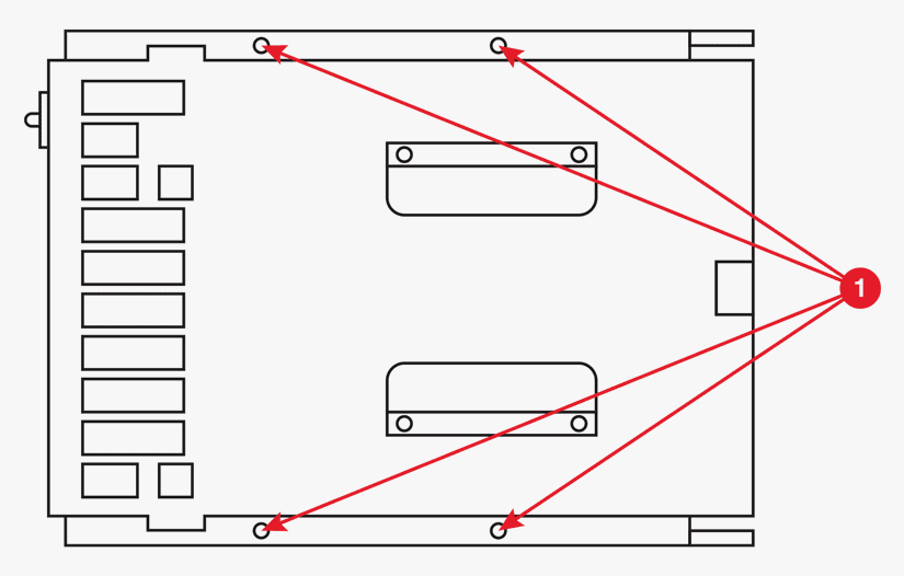 Figure 4
Identifying 20SC Revision A and B Drives
Hard Disk 20SC Revision A and Revision B drives must be replaced like-for-like. To differentiate between drive versions, check the location of the circuit boards when the drive is installed in an internal frame. For Revision A drives, the component side of the board is up (Figure 5, #1); for Revision B drives, the solder side is up (Figure 5, #2).
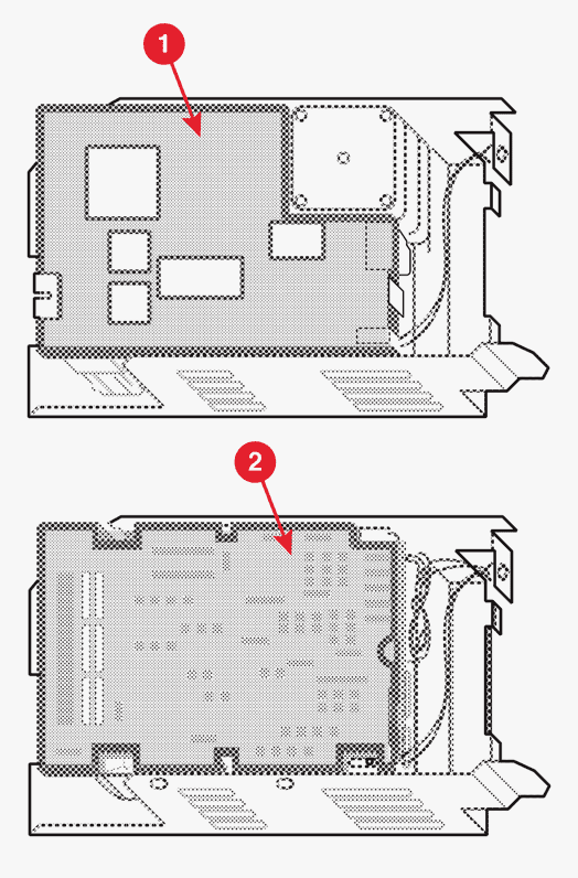 Figure 5 - Top Rev A, Bottom Rev B. The Hard Disk 20SC Version A drive and the Hard Disk 20SC Version B drive are identical, but these drives must be replaced like-for-like.
Reconfiguring Service Modules
The external 20 MB drive and 160 MB 5.25 drive service modules are shipped in a frame that fits inside the external case. If you are replacing one of these drives, go to the Replace procedure. If you are replacing any other 5.25-inch or 3.5-inch external drive, you must modify the service module and transfer it to the mounting frame. Perform the reconfiguration procedure that is appropriate for the size drive you are replacing.
Reconfiguring 5.25-inch Drives
Reconfigure a 5.25-inch drive assembly as follows:
Remove the four screws from the internal mounting frame, and remove the drive. At the time, the internal frame was used to return the defective drive to Apple.
Disconnect the three resistor packs (Figure 6, #1) from the controller board. To do this, use needlenose pliers and pull the resistor packs straight up.
Disconnect the power cable (Figure 6, #2).
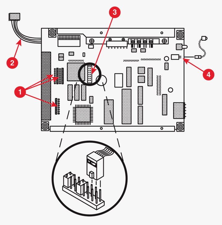 Figure 6
The SCSI connector is an unkeyed double row of sixteen pins. Be sure to install the SCSI cable with its tab (“key”) pointed toward the large 50-pin SCSI connector at the back of the controller board.
Connect the SCSI select cable (from the mounting frame) to the SCSI select cable connector (Figure 6, #3) on the controller board. Connect the SCSI cable to the three pairs of pins closest to the center of the board (see detail drawing). (Leave the small black jumpers on the other pins.)
Position the mounting frame over the bottom (board side) of the hard disk, and connect the LED cable connector to the controller board (Figure 6, #4). Be sure the tab on the cable connector is up and the wires are pointing down.
Align the mounting holes in the hard disk to the holes along the outside edges of the mounting frame, and install four screws.
Reconfiguring 3.5-inch Drives
Reconfigure a 3.5-inch drive assembly as follows.
Note: The 3.5” 160 MB drive is available only as an internal drive, and it is available only in the Macintosh IIfx and Macintosh IIci.
Remove the four screws from the internal mounting frame, and remove the drive assembly. At the itme, the internal frame was used to return the defective drive to Apple.
Disconnect the three resistor packs (Figure 7, #1) from the controller board. To do this, use needlenose pliers and pull the resistor packs straight up.
Disconnect the power cable (Figure 7, #2). (On some drive assemblies, the power cable is located on the opposite side of the hard disk.)
Identify the graphic (Figure 7 or 8) that shows the SCSI connector configuration (Figure 7, #3 or Figure 8, #1) of your hard disk assembly.
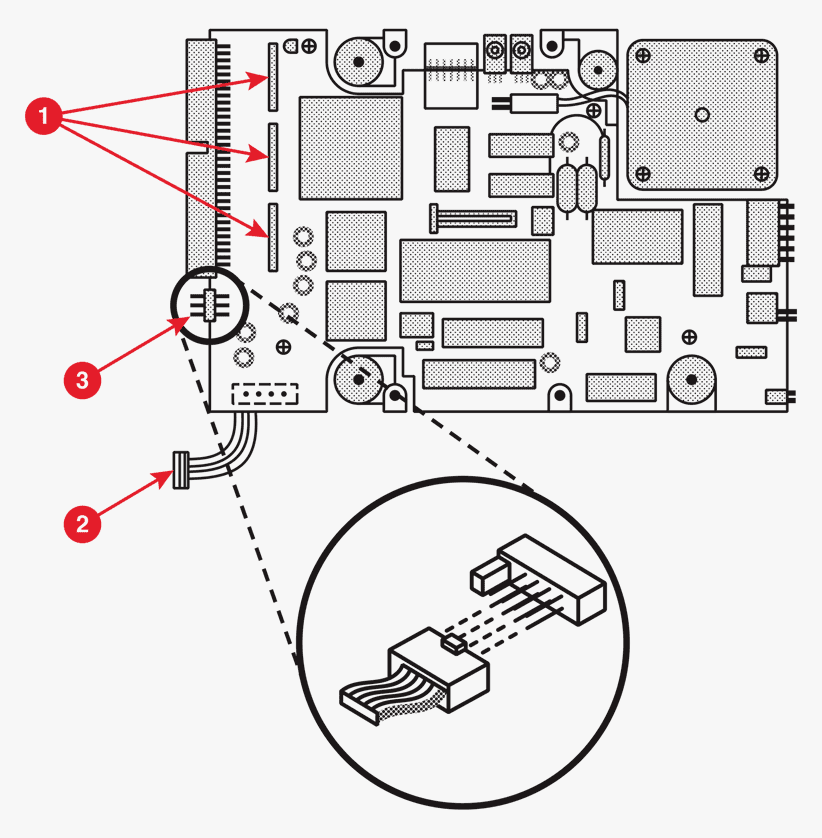 Figure 7
You must connect the SCSI select cable to six unkeyed connector pins on the controller board. The SCSI connectors differ in design and location between drive models. For models represented by Figure7, be sure to install the SCSI cable with its tab (“key”) pointing up. For models represented by Figure 8, be sure to install the SCSI cable with its tab pointing toward the outside edge of the controller board.
- Connect the SCSI select cable to the SCSI select connector on the controller board. Orient the cable connector as follows:
Figure 7: Attach the SCSI cable connector (tab up) to the three pairs of pins nearest the outside edge of the board. On some models, one or more of the three outside pairs of pins may have small jumpers installed; if so, remove the jumper(s).
Figure 8: Attach the cable connector (tab out) to the three outermost pairs of pins on the 12-pin connector (the three pairs of pins nearest the large, 50-pin SCSI connector).
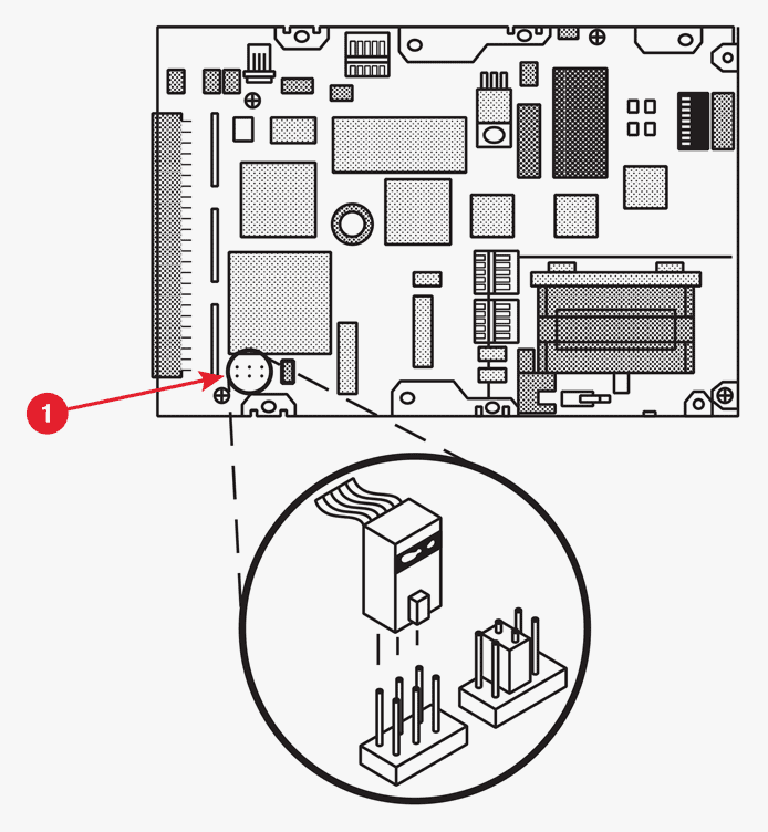 Figure 8
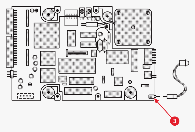 Figure 9
Position the mounting frame over the bottom (board side) of the hard disk, and connect the LED cable from the frame to the LED connector on the controller board (Figure 9, #1). Be sure the tab on the cable connector is pointing up and the wires are pointing down.
Align the mounting holes in the hard disk to the mounting holes nearest the center of the mounting frame, and install four screws.
Note: Use the internal (service module) frame to return the defective drive to Apple.
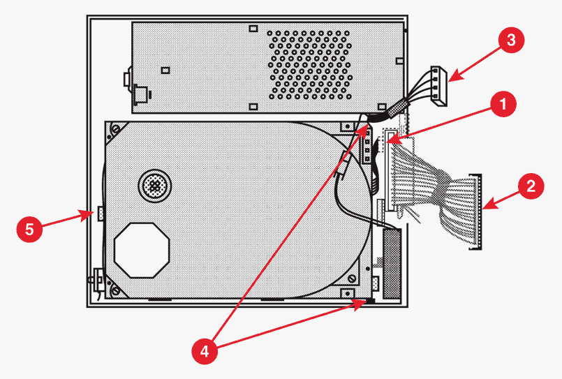 Figure 10
Connect the SCSI select switch connector (Figure 10, #1).
Connect the HDA-to-case cable (Figure 10, #2) to the hard disk assembly, and close the end tabs.
Connect the power supply connector (Figure 10, #3).
Note: On some hard disk assemblies, the power supply connector is located on the opposite side of the hard disk.
Slide the hard disk assembly toward the small tabs (Figure 10, #4) on the case bottom until the back edge of the metal frame is in place under the tabs.
Push back the holding tab (Figure 10, #5), and carefully settle the hard disk assembly into place.
Replace the case top.
SCSI SELECT SWITCH CABLE
Materials Required
Small flat-blade screwdriver No. 2 jeweler’s screwdriver
Remove
To remove the SCSI select switch cable:
Remove the case top.
Remove the hard disk assembly.
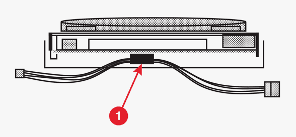 Figure 11
- Slide the cable out of the holding clamp(s) (Figure 11, #1) attached to the mounting frame. (On one type of clamp, you may need to use a small screwdriver to break the adhesive before you can slide the cable out.)
Replace
To replace the SCSI select switch cable:
Lift up (or open) one side of the holding clamp(s) (Figure 11, #1) that is attached to the mounting frame, and slide the cable into place. Make sure the cable is routed as shown.
Connect the SCSI select switch cable connector to the controller board. For more information about correctly connecting the SCSI select switch, see “Reconfiguring Service Modules.”
Replace the hard disk assembly .
Replace the case top.
LED CABLE ASSEMBLY
Materials Required
No. 2 jeweler’s screwdriver Small torx screwdriver (for the 160SC only)
Remove
To remove the LED cable assembly:
Remove the case top.
Remove the hard disk assembly.
If you are repairing a Hard Disk 160SC, remove four screws (Figure 12, #1) and pull the end bracket with LED cable (Figure 12, #2) off the hard disk assembly. Use the small torx screwdriver.
 Figure 12
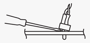 Figure 13
- Pry the small plastic retaining ring from around the LED holder with a jeweler’s screwdriver (Figure 13). Slide the retaining ring up the wires and out of the way.
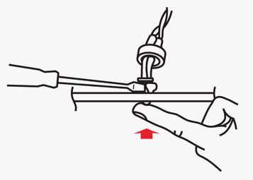 Figure 14
Press the face of the LED toward the inside of the metal frame while gently prying apart the LED holder with the screwdriver until the LED snaps free of the metal frame (Figure 14).
Disconnect the LED connector from the hard drive assembly, and remove the LED cable assembly.
Replace
To replace the LED cable assembly:
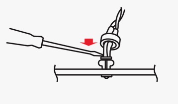 Figure 15
- If necessary, slip the LED into its holder and snap it into place with a jeweler’s screwdriver (Figure 15).
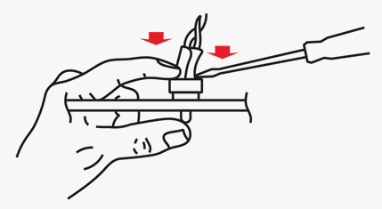 Figure 16
Slide the retaining ring down the wires and position it around the LED holder. Push the ring back into place with the screwdriver (Figure 16).
Connect the LED cable to the LED connector on the controller board.
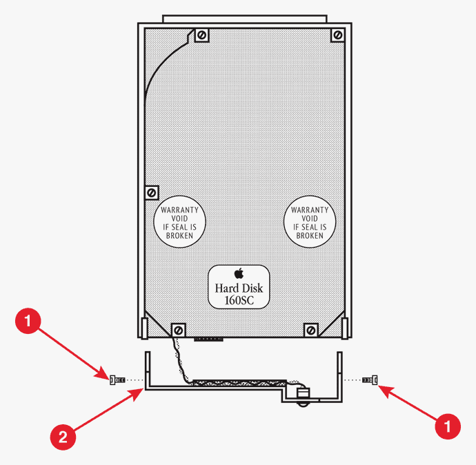 Figure 17
For 160SC hard drives, replace the end bracket (with attached LED cable) (Figure 17, #1) on the hard disk assembly, and install four screws (Figure 17, #2). Use the torx screwdriver.
Replace the hard disk assembly.
Replace the case top.
FAN FRAME
Materials Required
Medium flat-blade screwdriver No. 2 jeweler’s screwdriver
Remove
To remove the fan frame:
- Remove the case top.
 Figure 18
Push back the large holding tab (Figure 18, #1) and pull up the hard disk assembly (with metal frame). Set the hard disk assembly on the front edge of the case so that you have room to work.
Open the end tabs (if present) on the HDA-to-case cable connector (Figure 18, #2) and disconnect the cable from the hard disk.
Disconnect the fan cable by releasing the little holding clip on the connector (Figure 18, #3).
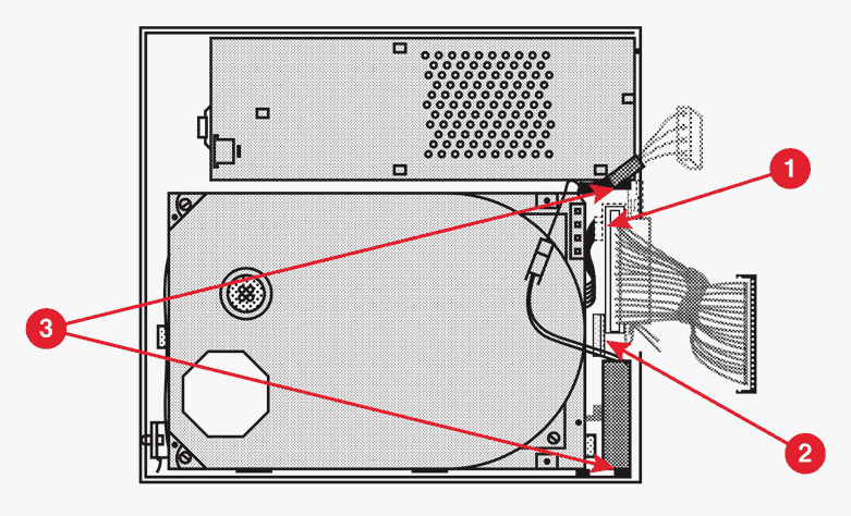 Figure 19
Disconnect the SCSI select switch cable connector (Figure 19, #1) from the SCSI select switch.
Using a flat-blade screwdriver, push back the plastic tab (Figure 19, #2) and lift out the metal fan frame (with fan, HDA-to-case cable, fan cable, and SCSI select switch attached).
Replace
To replace the fan frame:
Slide the side edges of the metal fan frame (with fan, HDA-to-case cable, fan cable, and SCSI select switch attached) into the center slots of the holding tabs (Figure 19, #3) located on the inside of the case bottom.
Push back the plastic tab (Figure 19, #2), and push the fan frame into place.
Connect the SCSI select switch cable (Figure 19, #1).
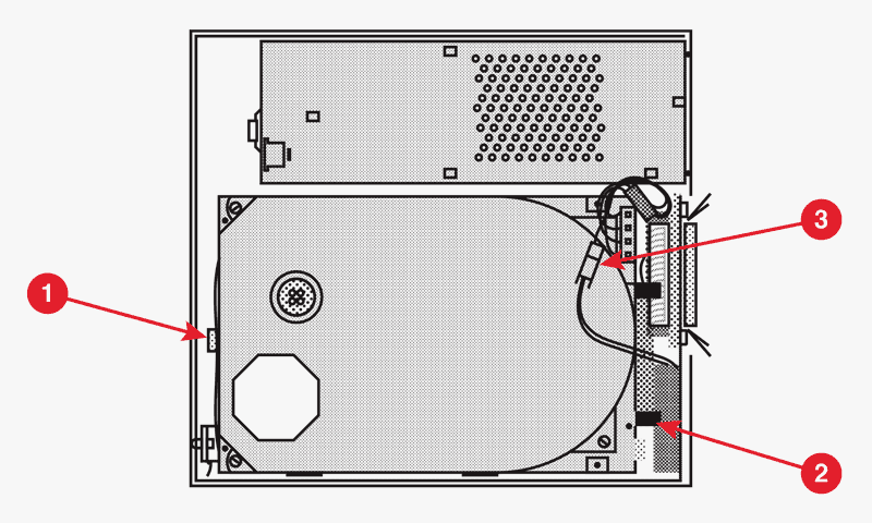 Figure 20
Connect the fan cable (Figure 20, #3). It fits only one way.
Connect the HDA-to-case cable (Figure 20, #2) to the hard disk and close the end tabs, if present.
Slide the hard disk assembly back into position, push back the holding tab (Figure 20, #1), and carefully settle the hard disk into place.
Replace the case top.
FAN
Materials Required
No. 2 Phillips screwdriver No. 2 jeweler’s screwdriver Medium flat-blade screwdriver
Remove
To remove the fan:
Remove the case top and fan frame.
Remove the HDA-to-case cable.
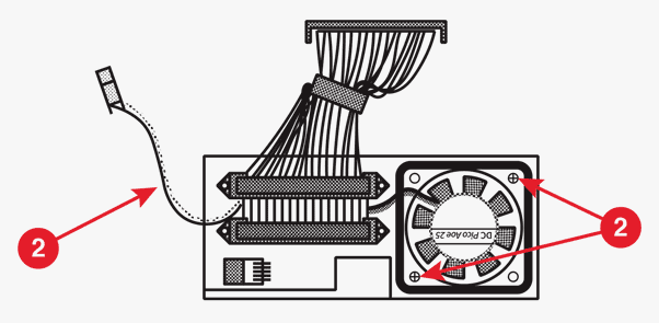 Figure 21
- Remove the two screws (Figure 21, #1) that secure the fan to the frame, and lift the fan free.
Replace
To replace the fan:
Set the fan in position in the frame as shown in Figure 21.
Replace the two screws (Figure 21, #1) that secure the fan to the frame.
Replace the HDA-to-case cable. Be sure to route the fan cable (Figure 21, #2) behind the HDA-to-case cable and between the connectors.
Replace the fan frame and case top.
HDA-TO-CASE CABLE
Materials Required
No. 2 Phillips screwdriver No. 2 jeweler’s screwdriver Medium flat-blade screwdriver
Remove
To remove the HDA-to-case cable:
Remove the case top.
Remove the fan frame.
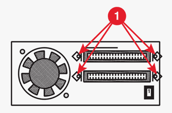 Figure 22
- Remove the four screws (Figure 22, #1) that secure the HDA-to-case cable to the frame, and lift the cable free.
Replace
To replace the HDA-to-case cable:
Lace the fan cable between the HDA-to-case cable and the two cable connectors. See Figure 22.
Set the cable connectors in place in the appropriate openings in the metal frame.
Replace the four screws (Figure 22, #1) that secure the HDA-to-case cable to the metal frame.
Replace the fan frame.
Replace the case top.
SCSI SELECT SWITCH
Materials Required
No. 2 Phillips screwdriver No. 2 jeweler’s screwdriver Medium flat-blade screwdriver
Remove
To remove the SCSI select switch:
Remove the case top.
Remove the fan frame.
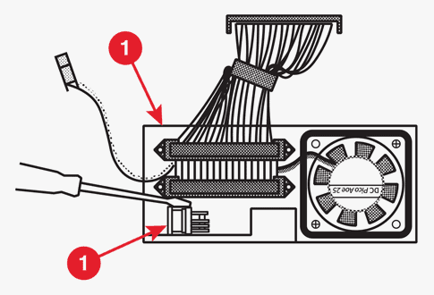 Figure 23
- Remove the switch (Figure 23, #l) by pushing it through the fan frame (Figure 23, #2) from the inside to the outside. To do this, push down on the switch and simultaneously depress the two plastic tabs-first on one side of the switch and then on the other. Use a jeweler’s screwdriver to depress both tabs at the same time.
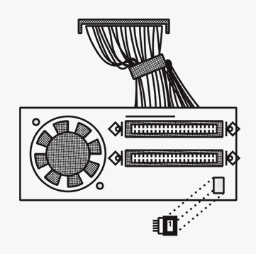 Figure 24
Replace
To replace the SCSI select switch:
Replace the switch on the fan frame. To do this, first insert the switch from outside to inside through the opening in the metal frame. Make sure the switch connector is aligned as shown in Figure 24. Then push up on the switch until it snaps securely into place on the frame.
Replace the fan frame.
Replace the case top.